


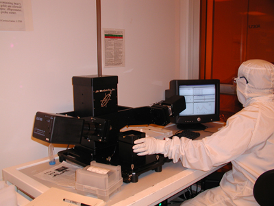
Woollam Ellipsometer M-2000D with NIR option
193-1690nm, 500 wavelengths
Perfect for semiconductor industry requirements. Measures at each lithography line – 193nm, 248nm, and 365nm.
Short wavelengths can increase sensitivity to ultrathin films, simultaneous collection at longer wavelengths ensures accurate thickness of transparent films. Long wavelengths enable characterization of transparent conductive oxides like ITO, telecommunications films, and films like SixGe1-x that are absorbing at shorter wavelengths. Also great for thick films and complex multilayers.
1.) Log on the tool using the LabAccess Terminal
2.) Power up the tool
a. Turn on the lamp power and the lamp ignition located on the M-2000DI located on the M-2000DI
b. The EC-400 should be on at all times
c. The computer monitor should be on at all times.
3.) Double click WVASE32TM icon on the desktop.
6 windows appear: Model, Generate Data, Fit,
Experimental Data, Hardware and Graph.
4.) Click anywhere in the Hardware window and click
Initialize. The WVASE32 Hardware log window appears. Enter a user name and click Ok.
appears.
5.) Enter a user name and click Ok.
6.) Place sample on stage. Make sure that the light
"a. is aligned with the aperture in the Output unit (MQD-160).
b. is focused on the sample. This can be done by placing a piece of paper on the sample stage to locate the light and aligning the sample with it."
7.) Turn the vacuum on. The switch is located on the lower left hand side of the Sample Stage.
8.) on the Setup menu select Load Samples.
9.) The Mount Sample window will appear. Click Ok. A window will appear with a red cross in the middle.
10.) Center the Cross at the origin using the two knobs located on the front and the right sides of the Sample stage. Press “Esc” on the keyboard when the red cross is close to the center. The "Hardware Sample Z-axis alignment" window appears and a
graph will be drawn on a different window.
11.) The error message "Insufficient intensity for Auto Alignment of Sample Z-stage" might appear. In this case, repeat steps 6 through 10 again to align the sample better.
12.) When "Repeat tilt-alignment and Z-alignment?" window appears, Select "Yes" to repeat the alignment process and do step 10 again. When the red cross is sufficiently close to the center, select "No" to "Repeat tilt-alignment and Z-alignment?" inquiry. 13.) On the Acquire data menu select Spectroscopic Scan. The "V.A.S.E Scan" window appears. Choose range and increment of angles. Typical values for different materials are listed below.
a. Metal, dielectrics: 60 to 75 degrees, increment=5°.
b. Silicon: 40 to 55 degrees, increment=5°.
c. "Revs/meas" box can be set to 10 (40 for better precision).
Click "Ok" after setting the required values.
14.) Select Yes/No to the "Save experimental data?" inquiry. Select "No" if you plan to save the model for this sample. If "Yes" is selected, save the data in the "DAT" folder.
15). Build model for the sample
a. Click anywhere on the "Model" window.
b. Select Add layer. A window appears, highlight the material of interest from the list and click "Ok". The Layer window will appear. Enter the desired thickness, select fit and click "Ok". If the selected material is Silicon, 1mm is a typical thickness value and the "fit" option is not active.
c. add an other layer by repeating step 15 b.
16.) Click anywhere in the “Generate data” window and select Generate data from the menu.
17.) Click anywhere in the "Fit" window. Select Normal Fits/Normal fit from the menu.
18.) To save the environment, Click on "Global" on the upper right hand corner of the desktop and select "Save current environment" from the dropdown list. Select the folder you want to save the environment.
19.) Log out of the tool using the LabAccess Terminal